Sign Designer
About
Sign Designer is an indirect 3D modeling tool tailored specifically for laser cutters, 3D printers, and CNC machines. Customization is facilitated through an intuitive menu with customizable parameters.
Simply the fastest low fuss method for creating small free-standing signs.
Features:
- Built in QR Code generator
- Url/Text
- WI-FI
- Phone Call
- SMS/Text
- vCard (Contact)
- Two different QR Code configurations:
- QR Code on Chip (Rectangle or Circle).
- QR Code on Sign/Backer
- QR Codes can be either ‘recessed’ (laser engraved) or ‘raised’ (3D printed)
- Lots of Configuration flexibility, making this a universal tool for both Laser/CNC and 3D Printing.
- 1 and 2 layer (frame) sign design
- Independent Sign, Frame, and Base thickness
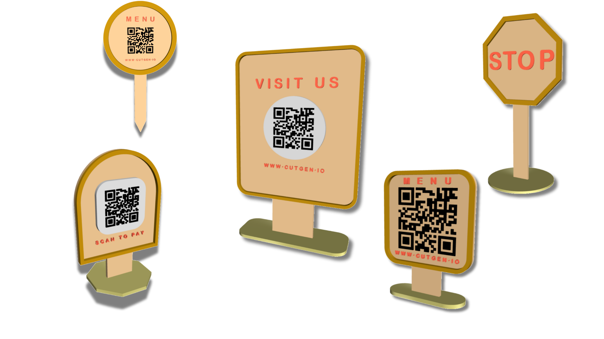
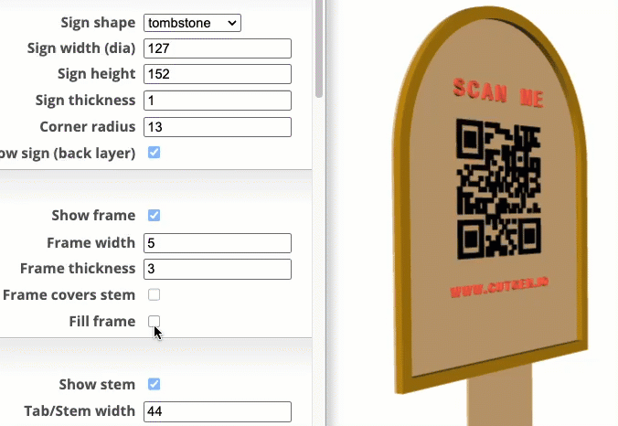
- 6 Different SIGN shapes
- Rounded Rectangle
- Tombstone
- Round (Circle)
- Oval
- Hexagon
- Octagon
- 6 Different BASE shapes
- Rounded Rectangle
- Tombstone
- Round (Circle)
- Oval
- Hexagon
- Octagon
- Custom length sign stem/tab.
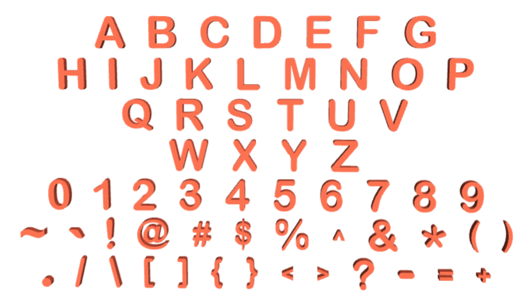
- One Block Font letter set of characters are limited to Uppercase only :
- ABCDEFGHIJKLMNOPQRSTUVWXYZ0123456789~`!@#$%^&*(),./[]{}<>?-=_+
- Independent letter size, thickness, and spacing
- Custom text above (Top text) and below (Bottom text) the QR Code
- 2D (SVG/DXF) or 3D (STL/OBJ) export
Designs can be exported as SVG (2D) or STL (3D) files. SVG can be used with laser cutters and CNCs. STL models can be imported into 3D slicer application to be used with 3D printers
The Sign Designer script operates within the powerful JSCAD environment—an open-source project that enables parametric 3D modeling through code. Check it out here: JSCAD.
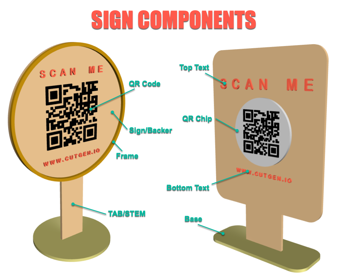
Sign Components
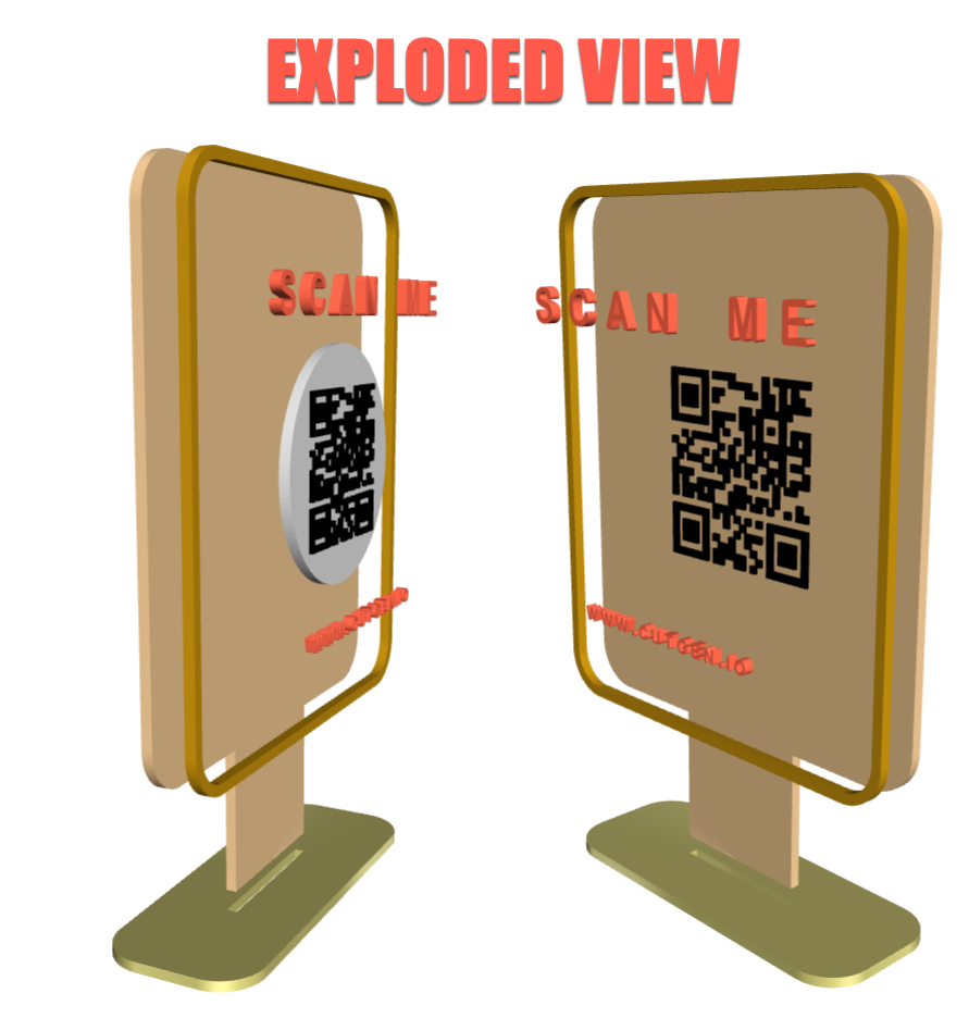
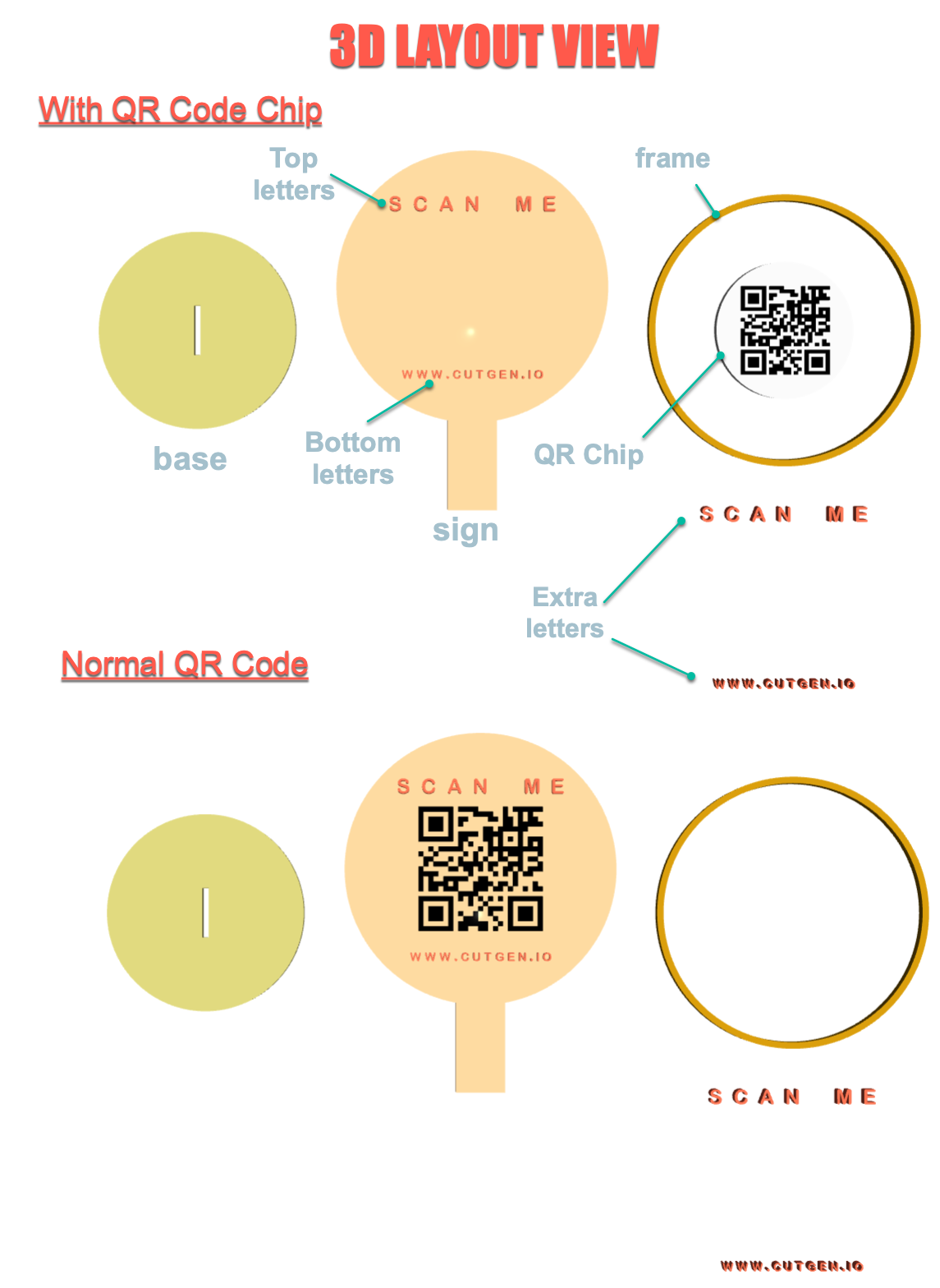
Exploded View
Letters
All Menu Parameters
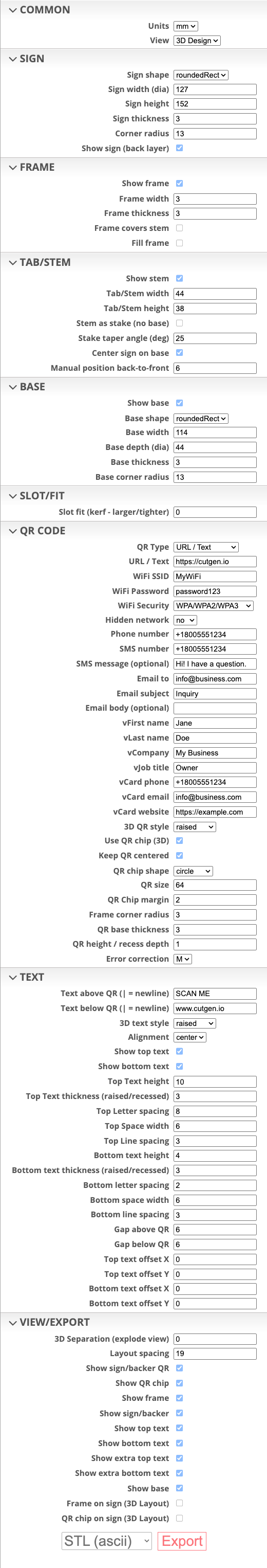
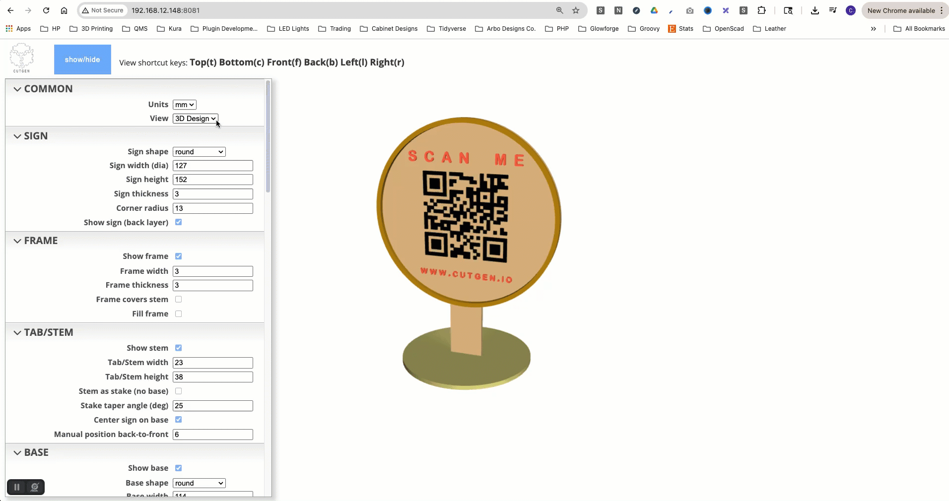
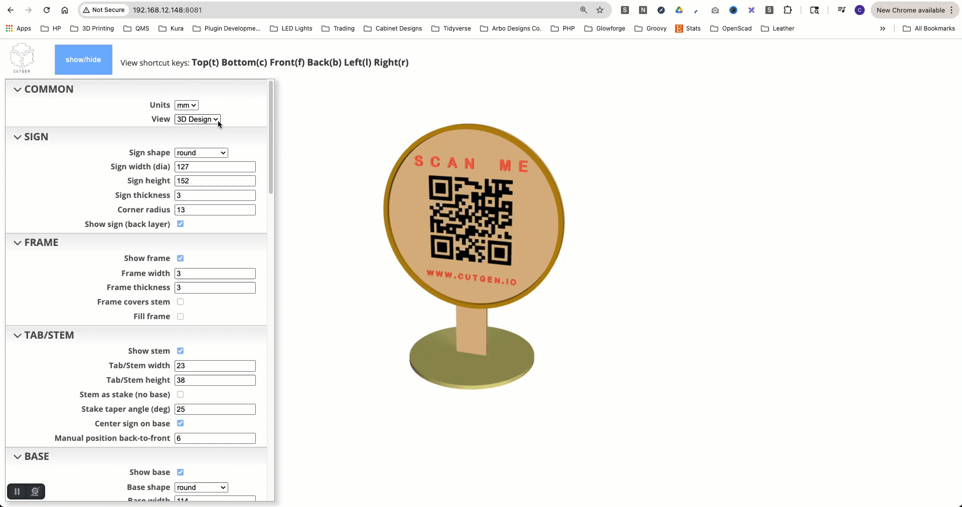
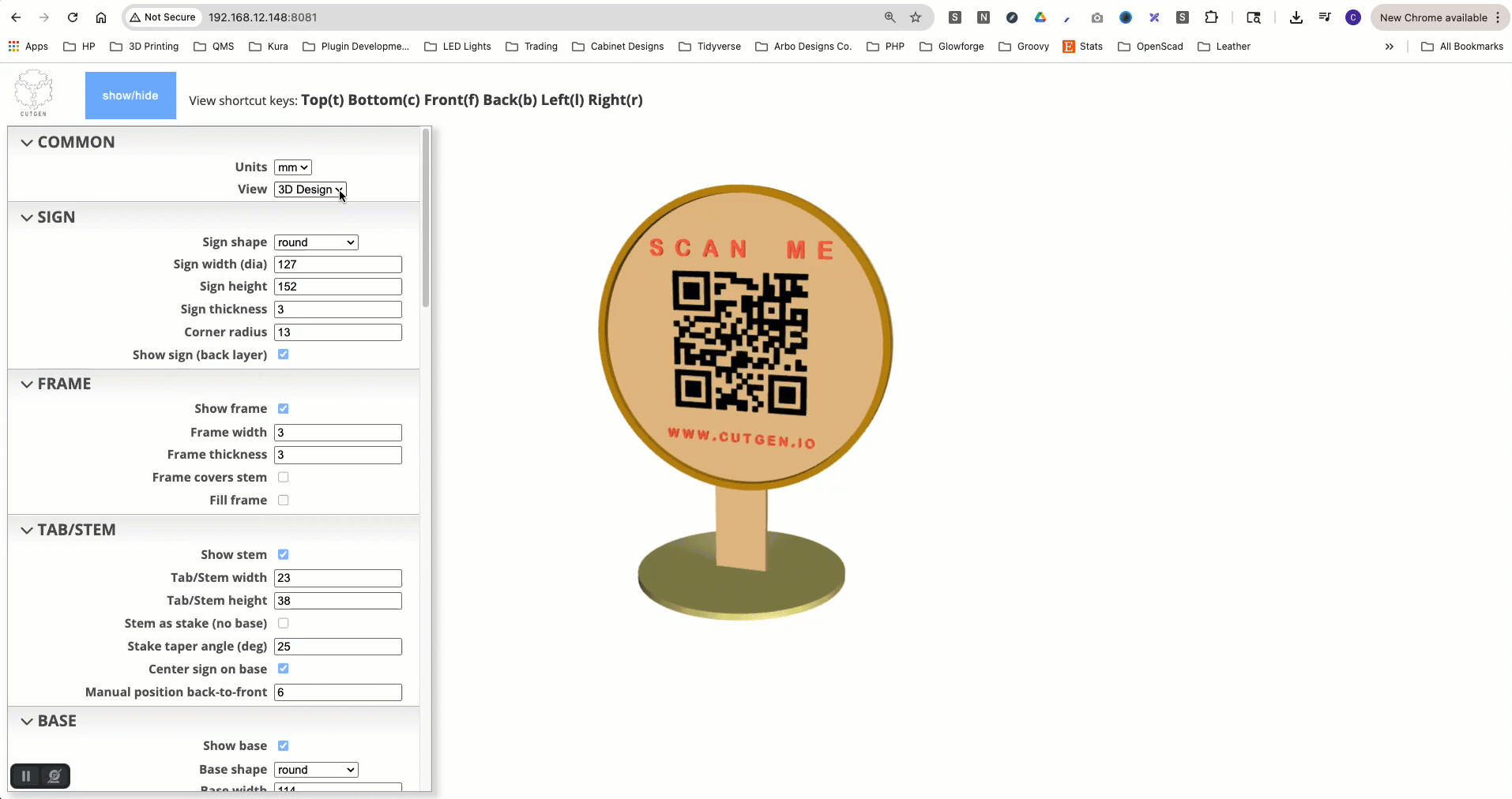
COMMON

Units
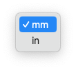
units of measure are in either in inches or mm millimeters.
While you can switch between inches and millimeters during design, the generator doesn’t automatically convert the input values to the new unit, so adjustments must be made manually. Cutgen offers separate design generator options for both ‘IN’ and ‘MM’ measurements, each with pre-set default values. For an optimal experience, we recommend choosing a single measurement unit and avoiding switching between them.
Views
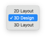
There are 3 different Views you will be working in depending on what you want to.
3D Design. Default view and is where you will spend 95% of the time while you build your sign. Changes to any of the menu item are observed in real-time on the right side view port.3D Layout. Used for Exporting STL which can be imported into a 3D slicer or mesh editing software. Mostly for 3D printing.2D Layout. Used for Exporting SVG which be imported into a laser cutting/CNC software such as LightBurn, Glowforge Carbide Create, etc.. Mostly for Laser Cutting or CNC operations.
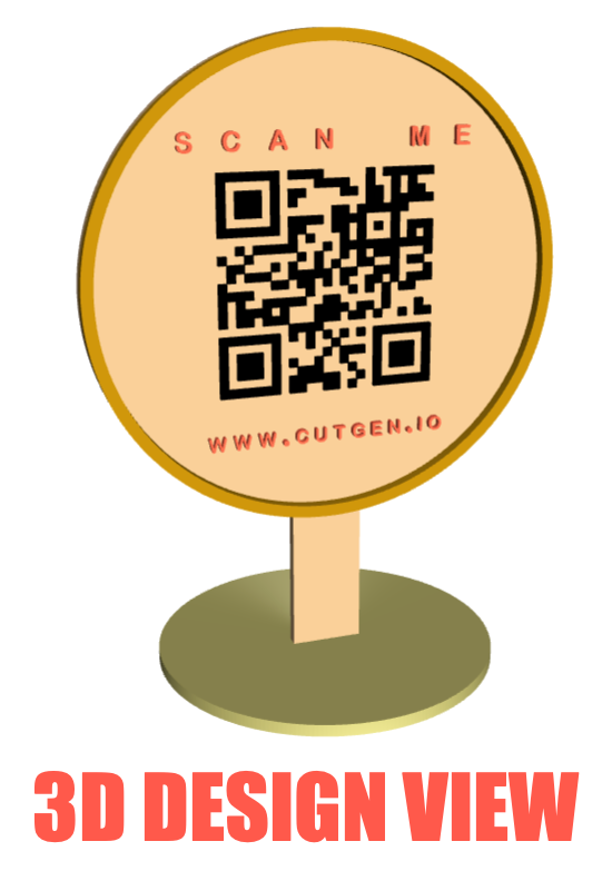
3D Design View
3D Layout View
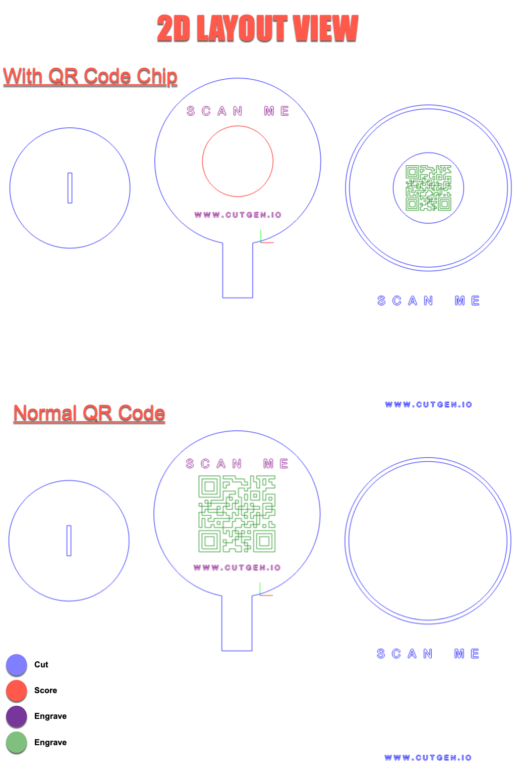
2D Layout View
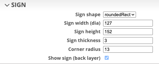
SIGN
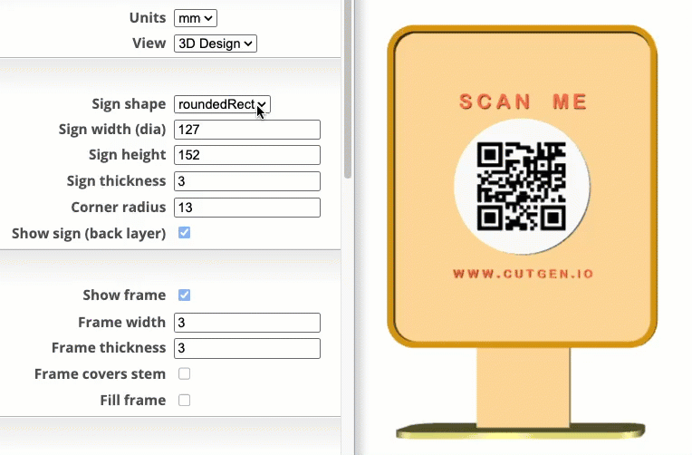
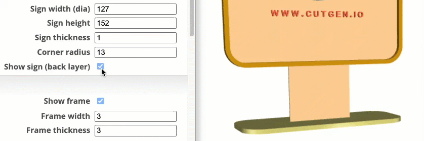
Sign shape
roundedRect and tombstone shapes are the only sign shapes which can be adjusted for width and height. All other shapes are re-sized using only the Sign width (dia) parameter.
Sign Width/height
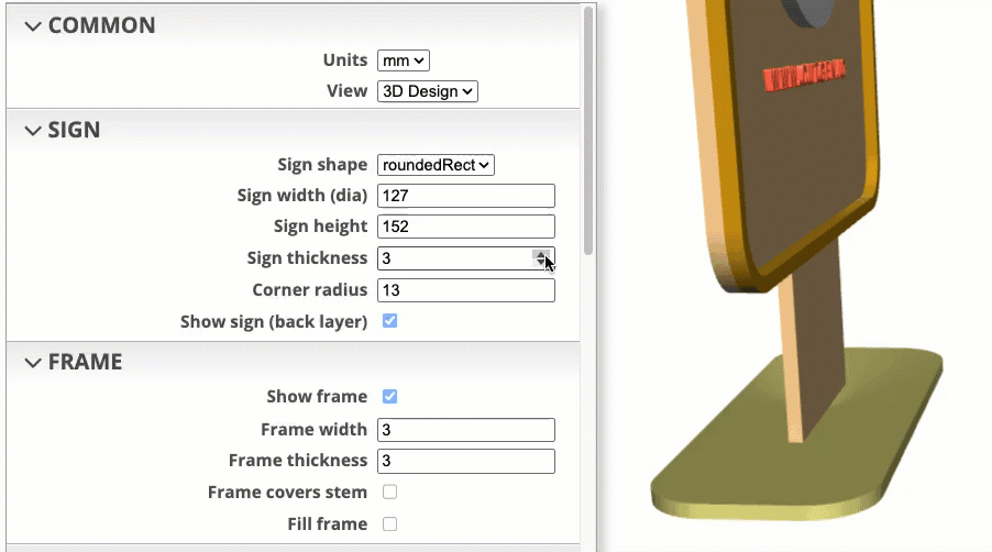
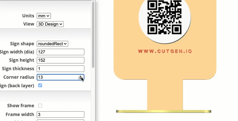
Sign Thickness
For laser cutters, set this to the thickness of the material as determined using digital calipers. For 3D printing, this can be any value.
NOTE: This thickness is critical for laser cutting if you want a good fit into the slot of the base.
Sign Corner Radius
Sign Show/Hide
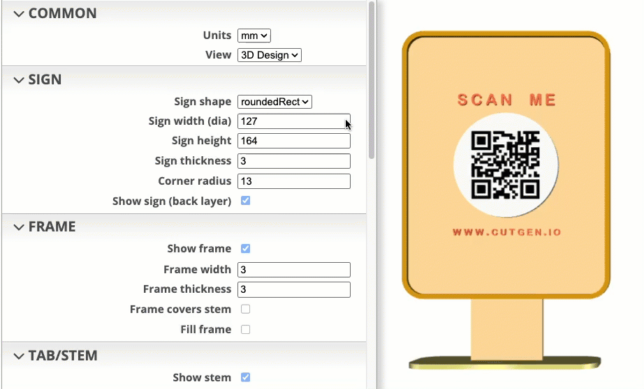
FRAME
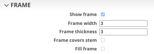
Show/Hide Frame
This is the width of the frame border.
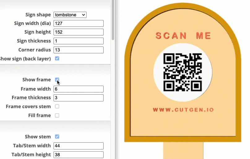
Frame Width
This is the width of the frame border.
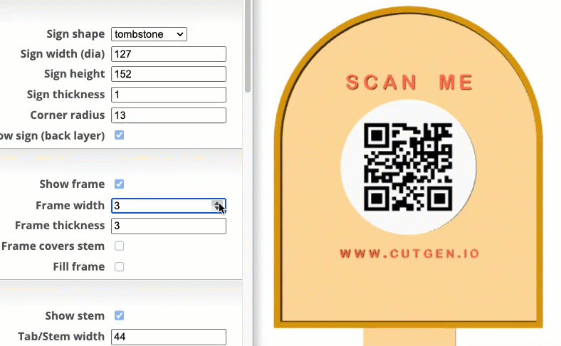
Frame Thickness
For laser cutters, set this to the thickness of the material as determined using digital calipers. For 3D printing, this can be any value.
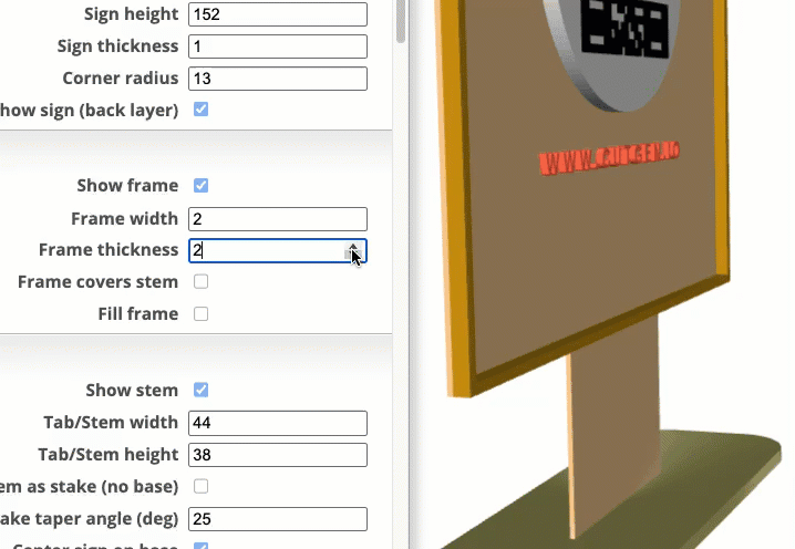
Frame Covers stem
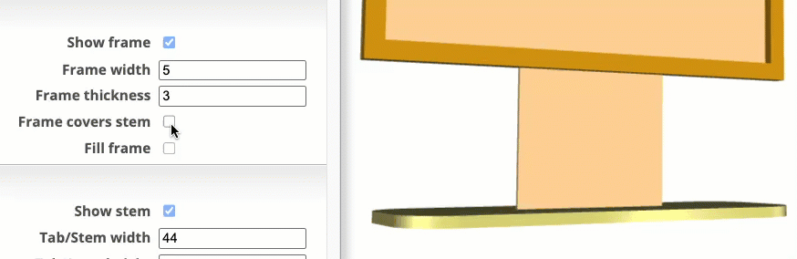
Fill frame
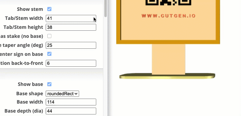
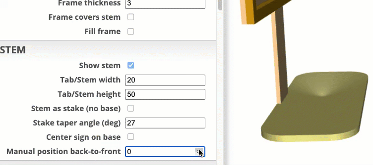
TAB/STEM
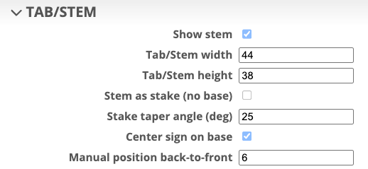
Show stem
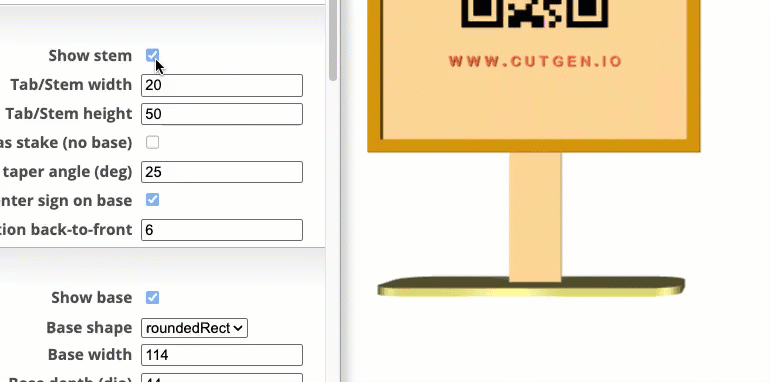
Tab/Stem width/height
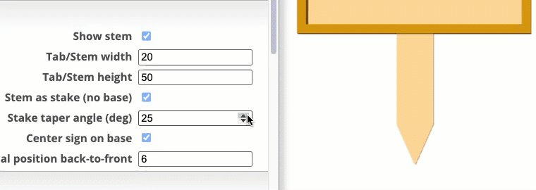
Stem as stake (no base)
Converts the stem and base into a stake, that can be used to press into soil/dirt.
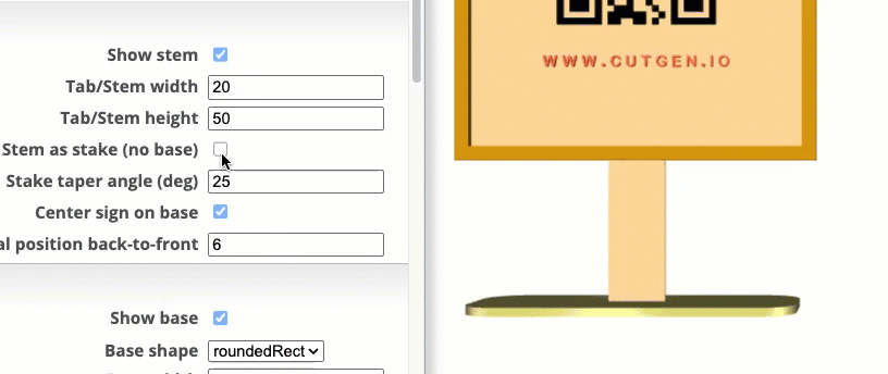
Stake taper angle (deg)
Center sign on base
Will center sign/stem front-to-back on the base.
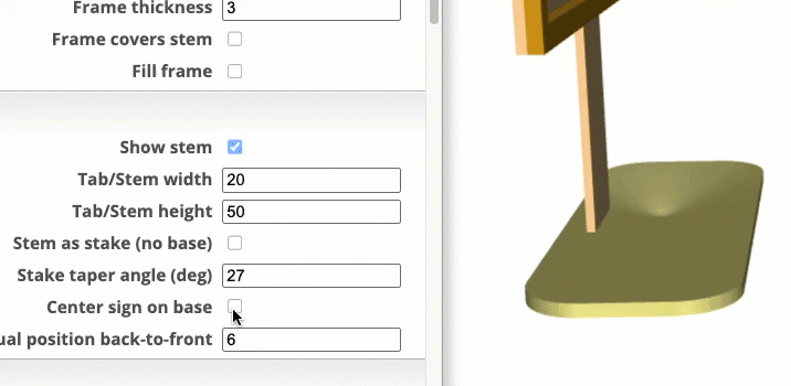
Manual position back-to-front
Allow for manual back-to-front positional control if needed.
NOTE: Center sign on base need to be ‘unchecked’
BASE
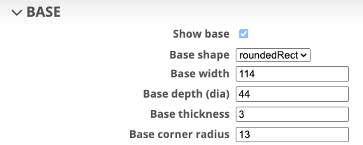
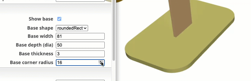
Show base
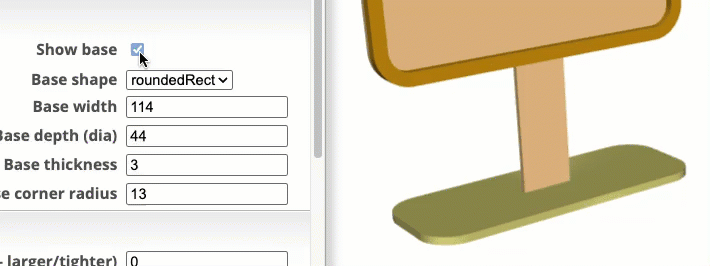
Base shape
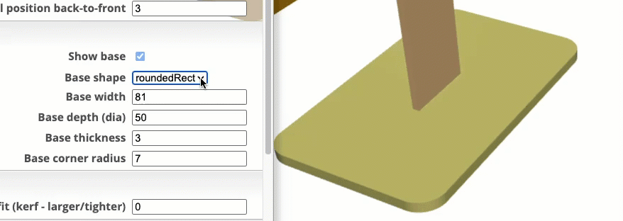
Base Width/Depth
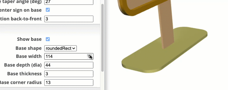
Base Thickness
For laser cutters, set this to the thickness of the material as determined using digital calipers. For 3D printing, this can be any value.
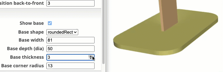
Base Corner Radius
Only applicable to the roundedRect shape.
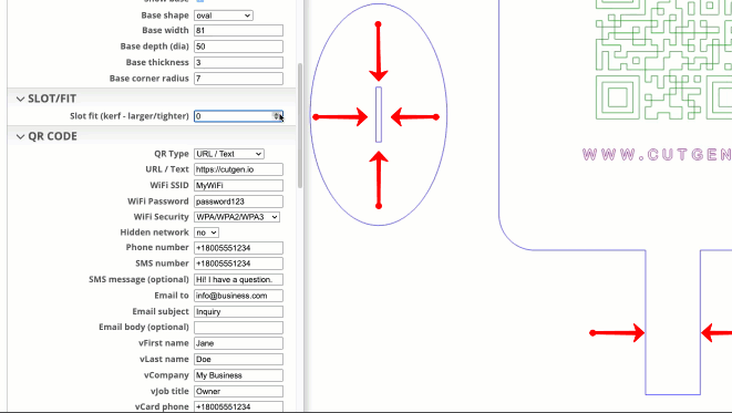
SLOT/FIT
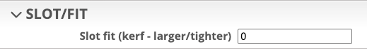
Slot fit (kerf - larger/tighter)
A laser kerf cut compensation needed for laser cutters so that slots and tabs fit correctly. Offsets are applied to the slot (cutout) of the base, and the width of the stem (tab). To determine KERF value, there are plenty of kerf tools on the internet that can be downloaded for free.
NOTE: In addition to this kerf compensation, ensure the sign thickness is accurate as measured with digital calipers, otherwise the stem-to-slot fit will not be correct. Material/Sign thickness affects the front-to-back clearance of the slot opening.
If the fit is too loose, increase the KERF value. Too tight, decrease the kerf value.
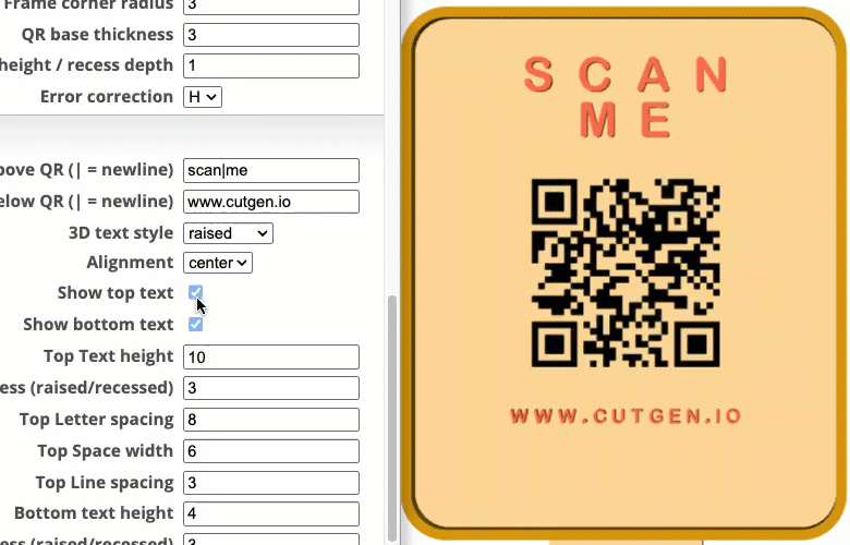
QR CODE
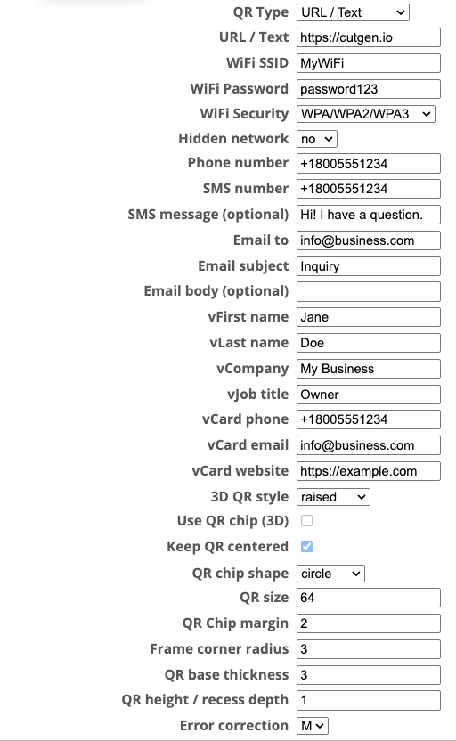
QR Type
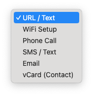
There are 6 different QR Code ‘types’
URL / Text
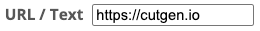
Enter either a URL address or any text string
Wifi Setup
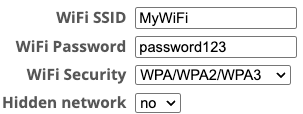
4 parameters. Enter your Wifi setup information using these parameters.
Phone Call
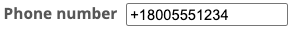
1 parameter. Enter phone number.
SMS / Text
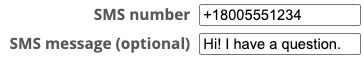
2 parameters. Enter phone number and the message.
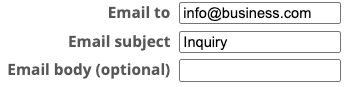
3 parameters. Enter to, subject, and optional body text.
vCard (Contact)
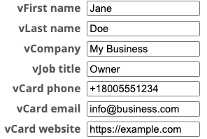
7 parameters. first/last name, company, title, phone, email, and website
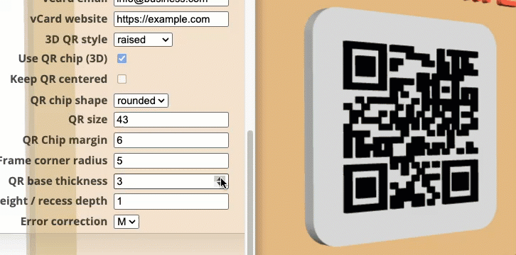
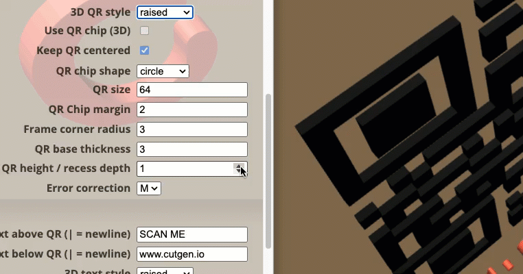
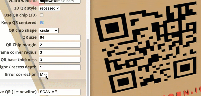
3D QR Style
The QR Code, either on the sign/back or the QR Code on the ‘chip’ can be either raised or recessed. Laser cutters/engravers will be recessed (material burned away). 3D printers can print either styles, but the ‘raised’ QR code will work much better, but some experimentation may be needed.
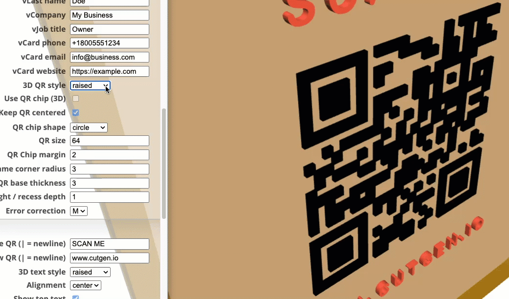
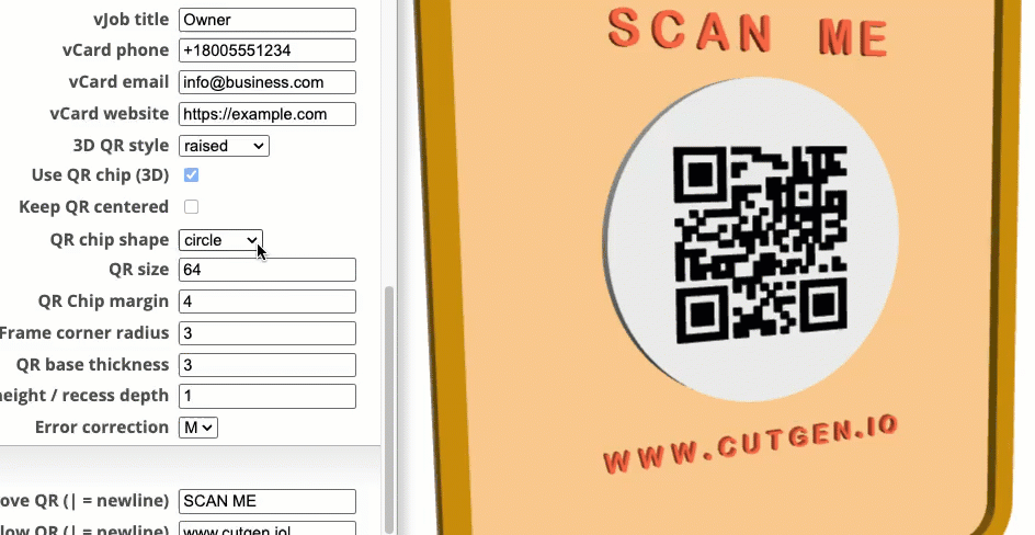
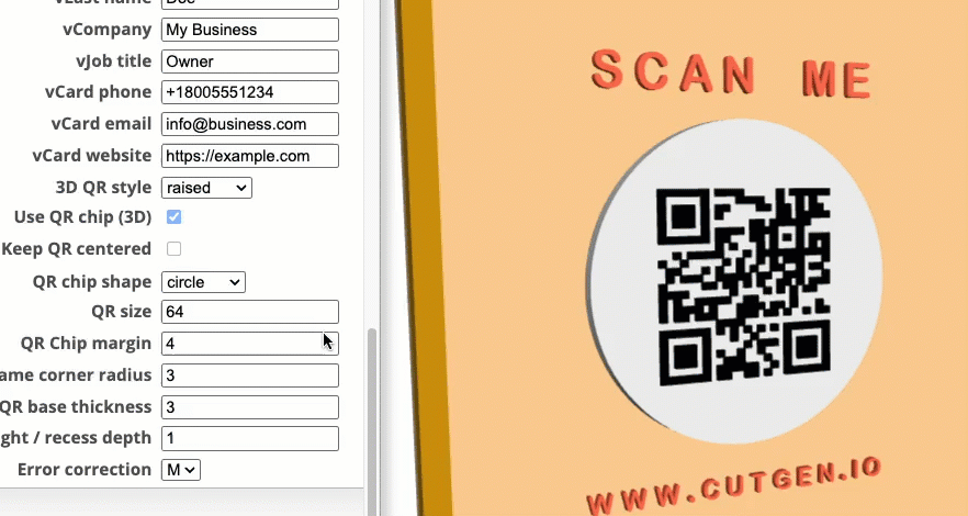
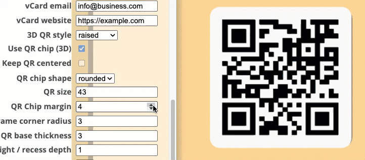
Use QR Chip (3D)
The QR Chip is an independent module that is either rectangular or circular. This can be glued onto the sign/backer for a decorative look. If this option is NOT Checked, the QR Code will be embedded/printed onto the sign/backer.
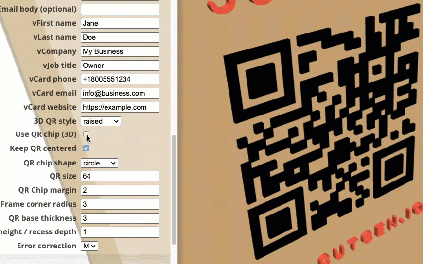
Keep QR centered
When checked, forces the QR Code on either the sign/backer or the QR chip centered on the sign/backer. If this is unchecked and top or bottom text is used, this influences the position of the QR code on the sign/chip and may be too high or too low, depending on the visual asthetic you are looking for.
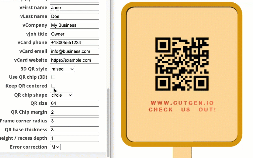
QR chip shape
The QR Chip is an independent shape (round or rectangular) that can exists as a separate element. There are two shapes: circle and rounded. Use QR Chip must be enabled.
QR Size
If Use QR Chip (3D) is checked, the QR size value will represent the size of the chip (rounded or circle). If Use QR Chip (3D) is unchecked, QR size will represent the size of the QR code imprinted on the sign/backer.
QR Chip margin
For use with the QR Chip only. The margin value is the space between the outer edge of the QR code and the outer edge of the chip object.
Frame corner radius
For use with the QR Chip only. This adjusts the corner radius of the rounded QR Chip shape.
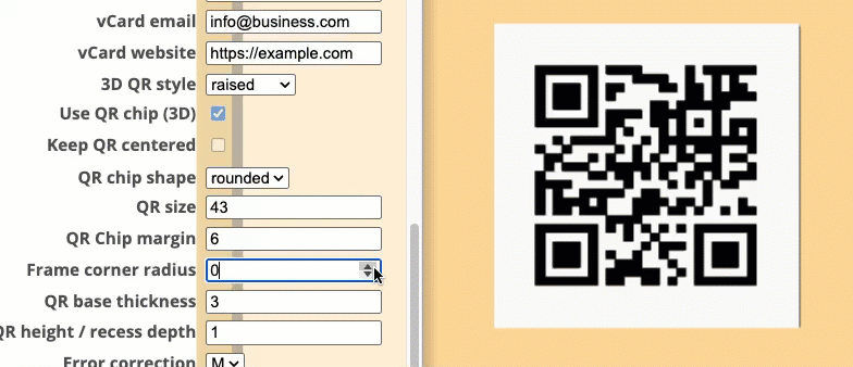
QR base thickness
For use with the QR Chip only. This set the thickness of the QR chip.
QR Height / recess depth
This sets the recess depth, if 3D QR Style = ‘recessed’, or set the raised qr height if 3D QR Style = ‘raised’
Error correction
M (medium) is default. Fine for most cases.
L (Low): ~7% data recovery (good for clean screens).
M (Medium): ~15% data recovery (a good balance).
Q (Quartile): ~25% data recovery (for moderate damage risk).
H (High): ~30% data recovery (maximum robustness, best for outdoors/industrial).
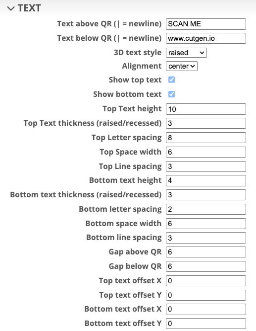
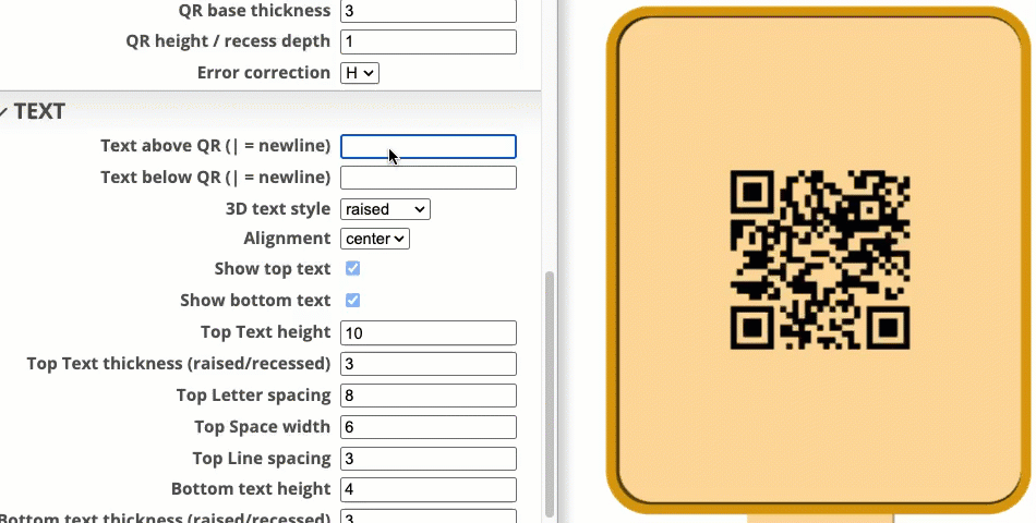
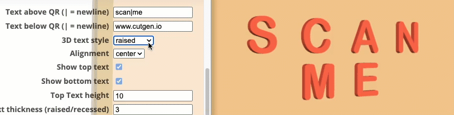
TEXT
This group handles the TOP (above QR Code) and BOTTOM (below QR Code) text properties. See Sign Components
Font/Letters
- One Block Font letter set of characters are limited to
Uppercase onlyABCDEFGHIJKLMNOPQRSTUVWXYZ0123456789~`!@#$%^&*(),./[]{}<>?-=_+ - TEXT parameters supply many properties for customization of size and position on the sign/backer.
Text Parameters
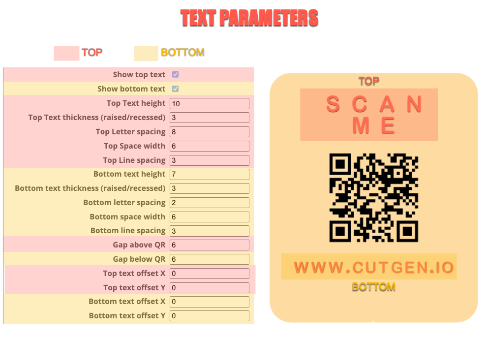
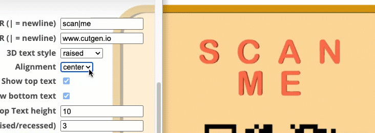
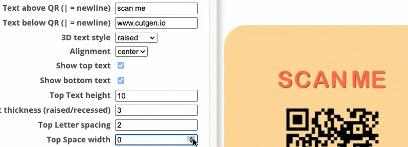
Text Above/Below QR Code
The QR Code is the center of focus and is located in the center of the sign/backer. There are TOP and BOTTOM text boxes allowing entry for custom text. Use the pipe ‘|’ to add a new line.
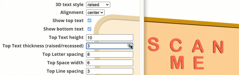
3D text style
The text can be raised above or recessed below the sign/backer.
Alignment
Text alignment options: left, center, right
Show Top/Bottom Text
Show/hide the bottom and top text options.
Top/Bottom Text height
Set the letter height of the top and bottom letters.
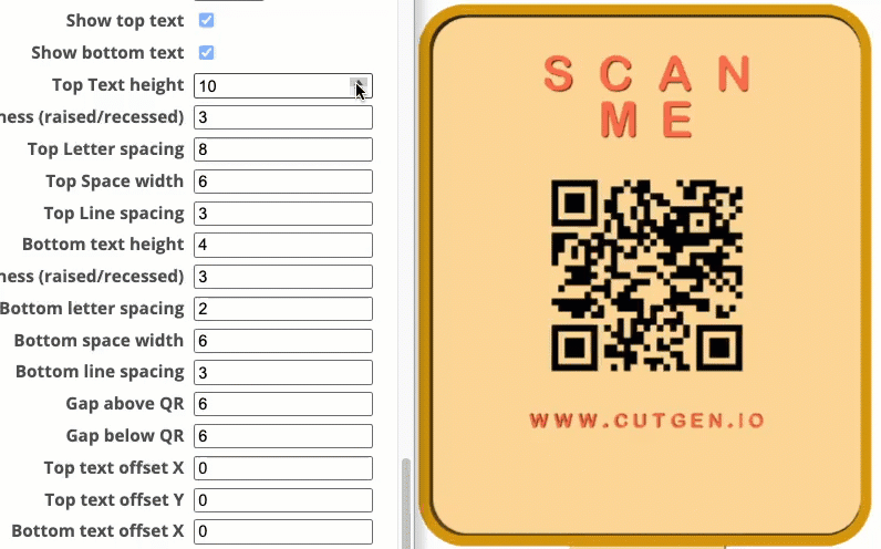
Top Raised/Recessed height
Used with 3D text style. Set the raised letter thickness and recessed depth into the sign/backer.
Bottom Raised/Recessed height
Used with 3D text style. Set the raised letter thickness and recessed depth into the sign/backer.
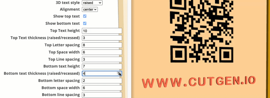
Letter Spacing Top/Bottom
Spacing gap applied between each letter
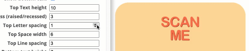
Space Width Top/Bottom
The width of each space entered into the Text above QR and Text below QR text boxes.
Line Spacing Top/Bottom
The gap between mutliline text.
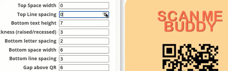
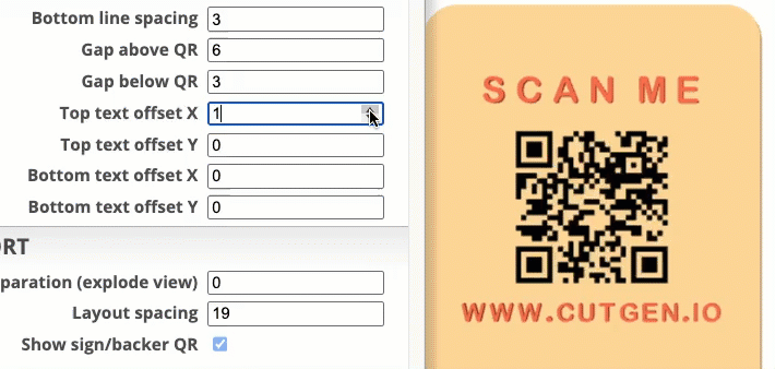
Gap Above/Below QR
The gap distance between the QR code and Top/Bottom letters.
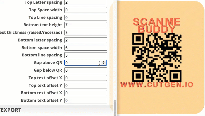
Text offset X/Y Top/Bottom Text
X/Y offset text positioning.
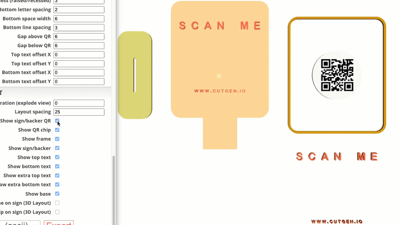
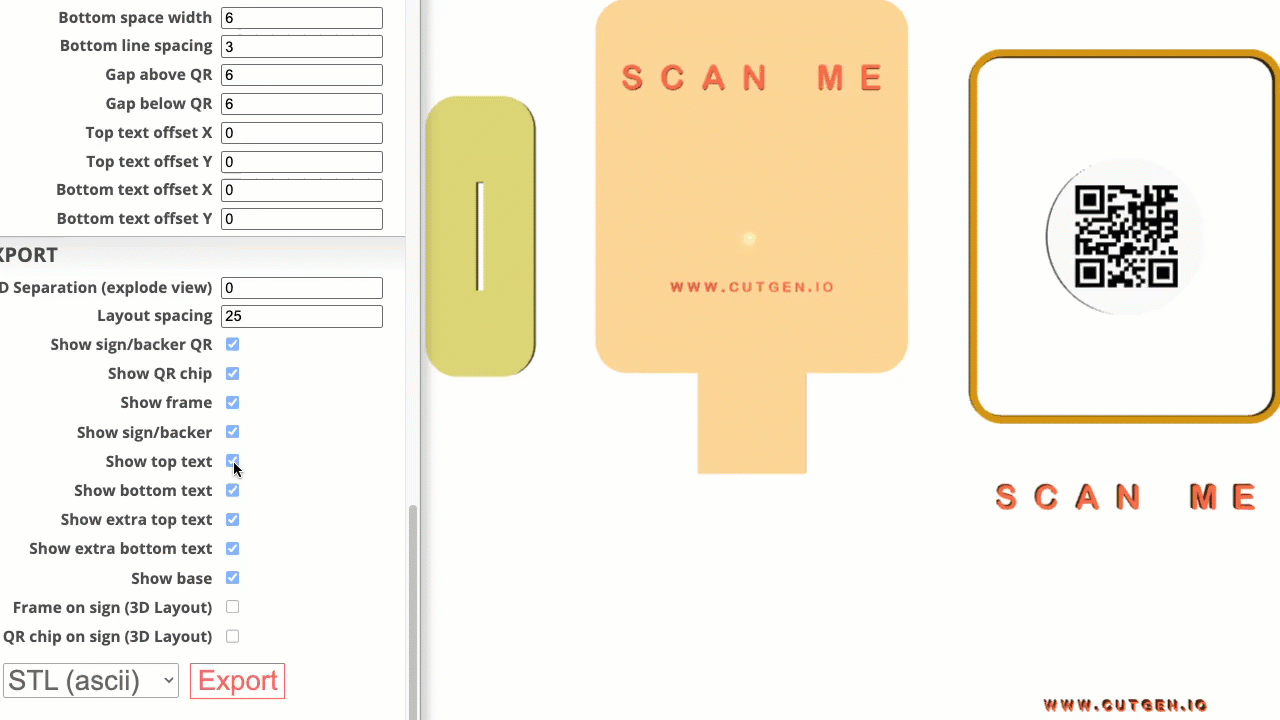
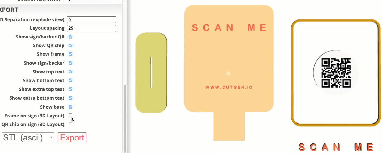
VIEW/EXPORT
This is the main menu group when you are ready to export your design to either STL (3D) or SVG (2D) for laser or 3D printing.
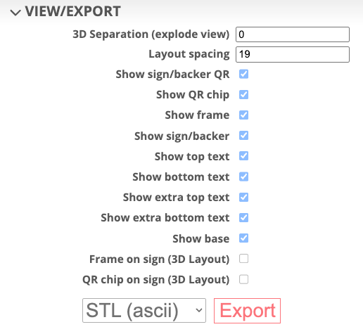
3D Separation (explode view)
In 3D Design view, you can separate each of the sign components for view or exporting.
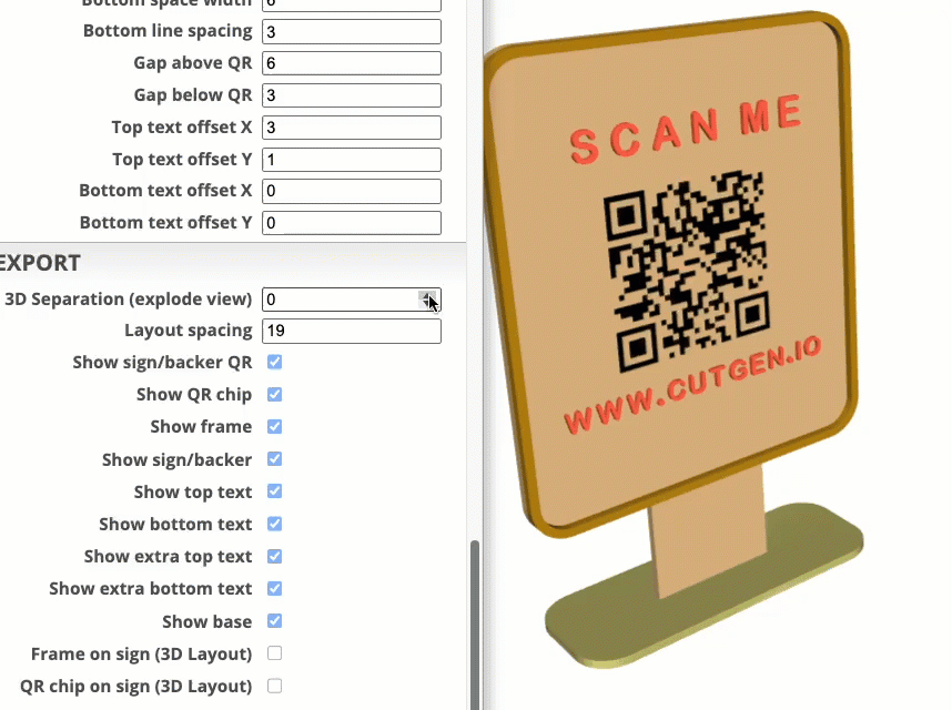
Layout spacing (2D/3D)
In 3D Layout view and 2D Layout view, you can add a gap between the various sign components.
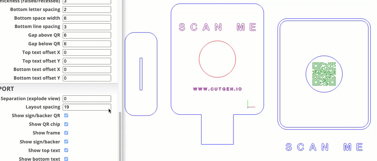
Show/Hide component checkboxes
In all views, there are several checkboxes (switches) in which allows the user to show/hide various sign components. This is mostly useful when EXPORTING out to STL or SVG file formats and want control over what is exported. What you see in the view, is what gets exported.
Part 1
Part 2
'extra' top and bottom text is located underneath the frame. This was added in case the user wanted to print or cut a 2nd set of letters to be applied/glued to the sign/backer. Additonal options to provide different aesthetics.
Part 3
Frame on sign (3D Layout) and QR Chip on sign (3D Layout) were added added for 3D printing. This allows the either the frame or the QR chip to be integrated into the sign/backer and then can be sliced as one assembly and printed on a 3D printer. This adds more flexibility to exporting options.
Laser Cutter User’s Guide
Here are some general guidelines and things to think of if you will be cutting and engraving signs on a laser cutting machine.
Measure material thickness using digital calipers. Accurate thickness is critical if you want to have the base slot and tab to fit tightly.
If the sign is cut from one material, set the thickness values to be the same in all four of these locations.
QR Chip base thickness (only if QR Chip is enabled).
To ensure a tight, well-fitting slot/tab connection, be sure to accurately set the KERF compensation value. There are many free kerf-calibration tools available online.
So, if the tab/slot connection is too loose or too tight, either the material thickness or KERF compensation value is incorrect. Go back and verify each.
The 2D Layout View, the line color denotes the ‘suggested’ laser operation to be performed.
Here are the color operations:
Blue = cut
purple = engrave or score
green = engrave
red = score
To export to SVG follow this procedure.
Note: “Hidden” components in the 2D Layout, will not be included in the exported SVG.
3D Printer User’s Guide
Here are some general guidelines and things to think of if you will be printing signs on a 3D printer.
I’ve found that 3D raised text Top/Bottom letters and QR code, works better than the recessed option. Raised, I found works best with the slicer’s 'color change' option.
When exporting as STL to import into your slicer, there are a few menu considerations at export:
If you want the frame or QR Chip fully integrated into the model before slicing, use the
frame on signorQR chip on signoptions, otherwise you can export the frame or QR chip as separate parts in the 3D Layout view.When importing the STL into your slicer, be aware that if you split into parts, the QR code will be broken into its smaller pieces which may be problematic or hard to manage.
To export to STL follow this procedure.
Note: “Hidden” components in the 3D Layout, will not be included in the exported STL.
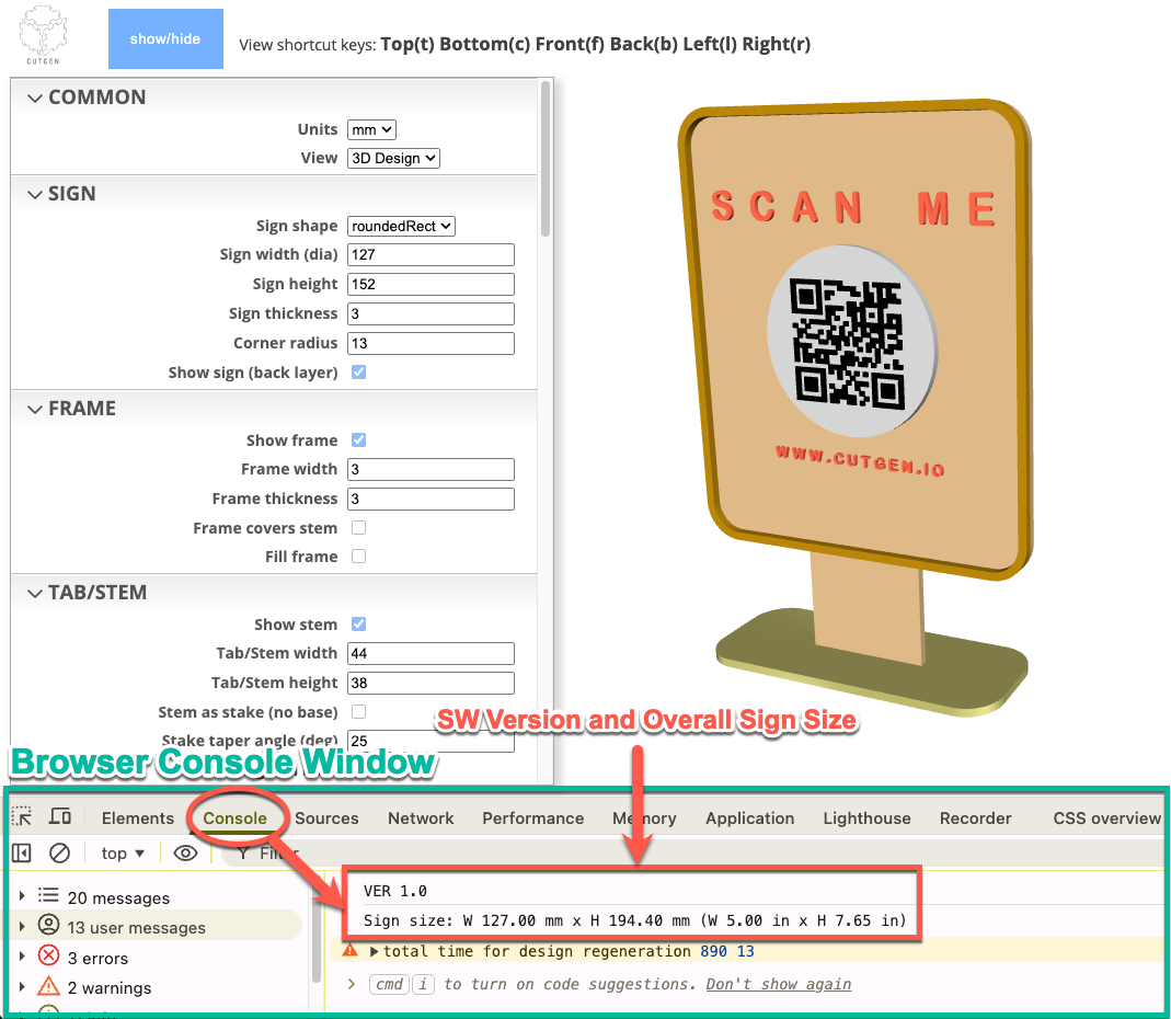
Sign Dimensions (Console Window Output)
After setting your final custom parameters, you can find the final board dimensions printed in the web browser’s ‘console’ window. How to access the console window depends on the browser type.
Chrome and Edge browsers
Using the main menu located at the top of the screen.
Click on ‘View’
Click on ‘Developer’
Click on ‘JavaScript Console’.
Board size in MM and IN will be displayed.
Firefox browser
Using the main menu located at the top of the screen.
Click on ‘Tools’
Click on ‘Browser Tools’
Click on ‘Browser Console’.
Board size in MM and IN will be displayed.
Safari browser
Using the main menu located at the top of the screen.
Click on ‘Develop’
Click on ‘Show JavaScript console’
Board size in MM and IN will be displayed.
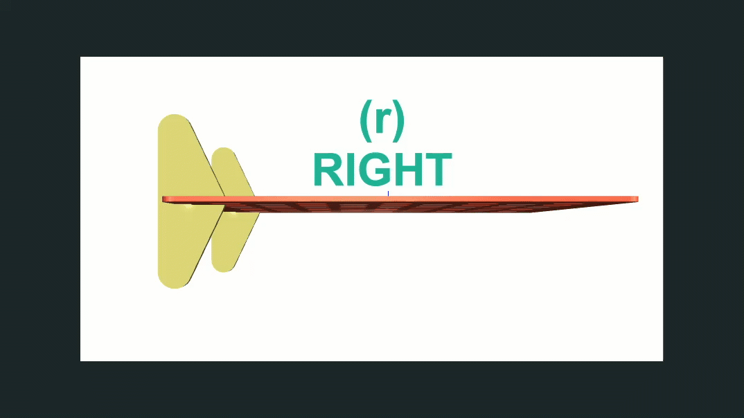
Shortcut ‘View’ keys
To enhance viewing and navigation of 3D and 2D objects, six shortcut keys are available.
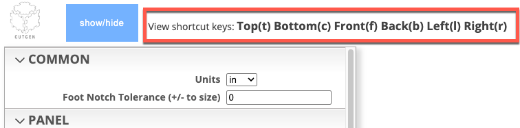
3D - Keyboard Shortcuts
Quick view keyboard shortcuts are provide. The view perspective is if you laid the panel down onto a flat surface and you are looking down at it.
Mouse Navigation
Pan (Move)
To pan or move a 2D or 3D model on the screen, press and hold the ‘SHIFT’ key, while at the same time hold down any mouse button (left, right, or scroll wheel). Drag the mouse to move the model around the 2D/3D space.
Orbit (rotate)
To rotate a 2D or 3D model on the screen, press and HOLD down any of the mouse buttons while dragging/moving the mouse.
Zoom
To zoom in or out within the 2D or 3D space, scroll the mouse wheel forward or backward.

Procedures
Export to SVG file
SVG is a native format for laser and CNC cutting machines. To export to an SVG file, follow these steps:
- Select ‘2D Layout’ from the ‘COMMON’ menu group.
- Press the ‘t’ key to display a top down view of the 2D layout.
- In the ‘VIEW/EXPORT’ menu group, select ‘SVG’ from the file type select dropdown box.
- Press the ‘Export’ button.
- Output SVG will be save in the ‘Downloads’ folder.
Export to STL file
STL is a native format for 3D printing machines. To export to an STL file, follow these steps:
Select ‘3D Layout’ from the ‘COMMON’ menu group.
In the ‘VIEW/EXPORT’ menu group, select ‘STL (ascii)’ or ‘STL (binary)’ from the file type select dropdown box.
Press the ‘Export’ button.
Output STL will be save in the ‘Downloads’ folder.
OBJ File Export for use in Blender
OBJ file format works much better in Blender than STL.
Select ‘3D Layout’ from the ‘COMMON’ menu group.
In the ‘VIEW/EXPORT’ menu group, select ‘OBJ’ from the file type select dropdown box.
Press the ‘Export’ button.
Output OBJ will be save in the ‘Downloads’ folder.